10+ avr block diagram
The diagram is shown below. Offline UPS block diagram.

The Atmega328p From Almost Nothing
Followings are the basics difference between them.

. It lacks only a DC power jack and works with a Mini-B USB cable instead of a standard one. The block diagram consist of a phase detector which acts as a phase comparator an amplifier and a low pass filter with the combination of the resistor 36 kilo ohm and capacitor C2. Timing diagram of MOV Instruction in.
All the 32 regis-ters are directly connected to the Arithmetic Logic Unit ALU allowing two independent registers to be accessed in. An integrator is connected in it and the capacitor discharges into this integrator or a low pass circuit. CALL Instructions and Stack in AVR Microcontroller.
The internal resistors act as a voltage divider network providing 23Vcc at the non-inverting terminal of the upper comparator and 13Vcc at the inverting terminal of the lower comparator. Likewise the receiver section includes a receive hold register shift register and control logic. Digi-Key is your authorized distributor with over a million in stock products from the worlds top suppliers.
But for a long time operating devices batteries could prove to be costly and complicated. Rated 1 in content and design support. Offline uninterruptible power supply block diagram.
You can either connect all the shown connections for uploading the program to check the working or you can assemble the bot completely and then proceed with the connections. 21 Block Diagram Figure 2-1. Microchips AVR-IoT Cellular Mini features Sequans Monarch 2 GM02S cellular module.
2543mavr1016 attiny2313 block diagram figure 2. The above block diagram shows a frequency to voltage converter. 14 Dec 20.
All the 32 registers are directly connected to the Arithmetic Logic Unit ALU allowing two independent regist ers to be accessed in one single instruction executed in one clock cycle. The frame structure is not configured the default is 8N1 eight data bits no parity bit and one. The output of the amplifier is fed back to the VCO.
Both ways the connections are very simple and you should be able to get it right. Log in or register to post comments. Satellite communications are related to the space mirrors because they assist us in activating the signals like internet data radio TV from one face of the earth to another face.
As the name says the voltage regulation is provided by shunting the current away from the load. PID controller design using Simulink MATLAB. When the input signal with high input impedance and low output impedance is applied to this counter then it will be fed to the amplifier to convert the signal into a square wave or rectangular wave for processing within the digital circuit.
The block diagram of a discrete transistor shunt voltage regulator is given below. These electrodes detect the small electrical changes that are a consequence of cardiac muscle. Timing diagram of MVI instruction.
Changing the speed of the car is one of the best examples. Block Diagram The Atmel AVR core combines a rich instruction set with 32 general purpose working registers. The best method used is in the form of an unregulated power supply a combination of a transformer rectifier and a filter.
UART Block Diagram The UART block diagram consists of two components namely the transmitter receiver that is shown below. Submitted by linkan on Tue 10312017 - 2059. Block diagram of online uninterruptible power supply.
Libero SoC Design Suite provides you with an integrated hardware tool suite incorporating RTL entry through programming a rich IP library complete reference designs and development kits. 21 Block Diagram Figure 2-1. Block Diagram of 8259 Microprocessor.
By executing powerful instructions in a single clock cycle the ATmega328PB achieves. The transmitter section includes three blocks namely transmit hold register shift register and also control logic. Lets now move towards a simple example regarding the working of a simple PID controller using Simulink.
The block diagram of the satellite communication system includes the following. It is an electrogram of the heart which is a graph of voltage versus time of the electrical activity of the heart using electrodes placed on the skin. This satellite communication system can be explained through three.
The block diagram of ADC is shown below which includes sample hold quantize and encoder. The circuitry of an AVR is complex and consists of all active and passive elements along with microcontrollers. The process of ADC can be done like the following.
Libero SoC Design Suite offers high productivity with its comprehensive easy-to-learn easy-to-adopt development tools for designing with our FPGA device families. Hi sir please send the Water level indicator using transistor. The circuit charges the capacitor to a certain level.
It has more or less the same functionality of the Arduino Duemilanove but in a different package. The block diagram of a simple PID controller is provided in the figure below Figure 2. Waveform reconstruction vertical plates horizontal plates cathode ray tube CRT horizontal amplifier time base circuitry trigger and clock.
In most applications the control input is not used so that the control voltage equals 23 V CC. First the analog signal is applied to the first block namely a sample wherever it can be sampled at an exact sampling frequency. Online UPS block diagram.
Timing diagram of INR M. THATHAS Thinpack Aluminum Electrolytic. Electrocardiography is the process of producing an electrocardiogram ECG or EKG a recording of the hearts electrical activity.
Hi sir please send the block diagram of water level indicator. Block Diagram The AVR core combines a rich instruction set with 32 ge neral purpose working registers. Refer Block Diagram of 555 timer IC given above.
Block diagram program counter program flash instruction register gnd vcc instruction decoder control lines stack pointer sram general purpose register alu status register programming logic spi 8-bit data bus xtal1 xtal2 reset internal oscillator oscillator watchdog timer timing and control. All low power system can be run with a battery. The block diagram and connection diagrams are shown in the figure below.
The block diagram of the digital storage oscilloscope consists of an amplifier digitizer memory analyzer circuitry. Advantages and Disadvantages of Microcontroller. The complete circuit diagram for this Fire Fighting Robot is given below.
The basic principle of the AVR is the same as a. This happens for all the cycles of the input waveform. ATmega328PB ATmega328PB Datasheet Introduction The picoPower ATmega328PB is a low-power CMOS 8-bit microcontroller based on the AVR enhanced RISC architecture.
The block diagram of the digital storage oscilloscope is shown in the below figure. The Arduino Nano is a small complete and breadboard-friendly board based on the ATmega328 Arduino Nano 3x. Unregulated Power Supply Diagram.
Frequency Counter Block Diagram Input. USART Block Diagram Clock Generator Transmitter Receiver Transmit Shift Register TXDATA Parity Pin Clock Data Parity TX RX Receive Shift Register RXDATA Buffer Sync Logic XCK XDIR TxD RxD. Above block diagrams are self explanatory.
Block Diagram of F-V converter. Pin 10 to Pin 17 Port 3.
Arduino Circuit Page 5 Microcontroller Circuits Next Gr

Schematic Diagram Of The Control Stage Download Scientific Diagram

Lovely Wiring Diagram Alternator Diagrams Digramssample Diagramimages Wiringdiagramsample Wiringdiagr Electrical Circuit Diagram Voltage Regulator Diagram

332 Voltage Regulator Replacement Weekend Freedom Machines

Typical Alternator Wiring Voltage Regulator Alternator Diagram

Schematic Diagram Of The Control Stage Download Scientific Diagram

10 General Electric Furnace Wiring Diagram Electrical Diagram Electric Furnace Washing Machine Motor

10 Multiple Effect Evaporator Diagram Of Multiple Effect Evaporator Pharmacy Images Medicine Images Free Human Body

Blank Tree Diagram Template Unique Wire Diagram Template Schematics Online Toyota Electrical Wiring Diagram Wire

10 Mitsubishi Car Alternator Wiring Diagram Car Alternator Mitsubishi Cars Alternator

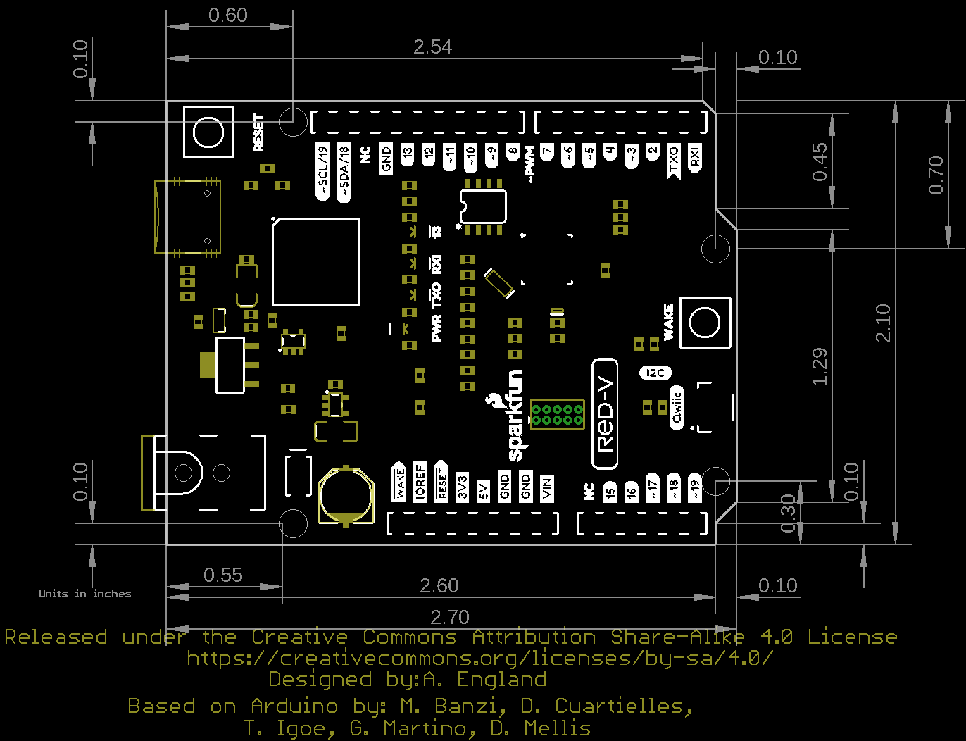
Sparkfun Red V Redboard Sifive Risc V Fe310 Soc Dev 15594 Sparkfun Electronics
Review And Measurements Of Nad T758 V3 Avr Page 8 Audio Science Review Asr Forum

Atmega32 Pin Diagram Javatpoint

10 Panasonic Car Radio Wiring Diagram Sony Car Stereo Panasonic Car Audio Car Stereo

Capacitor Circuits Capacitor In Series Parallel Ac Circuits Circuit Electronics Circuit Capacitor

332 Voltage Regulator Replacement Weekend Freedom Machines

Pin On Programming